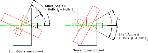
The calculations use procedures, algorithms and data from standards ANSI, ISO, DIN, BS and specialized literature. This section on helical gear mathematics shows the detailed solutions to many general helical gearing problems.
HELICAL GEAR DESIGN CALCULATOR MANUAL
The following excerpt is from the Revised Manual of Gear Design, Section III, covering helical and spiral gears. Drawings of an accurate tooth shape including data (X,Y coordinates). The article 'Helical Gear Mathematics Formulas and Examples' appeared in the May/June 1988 issue of Gear Technology.Supplementary calculations (calculation of parameters of the existing gear, temperature rise, design of shafts, check dimensions, new materials definition).Design of gearing for exact axis distance.


The helix angle references the axis of the cylinder, distinguishing it from the lead angle, which references a line perpendicular to the axis. Helix and lead angle are complementary their sum must equal 90 degrees. The terms “lead angle” and “helix angle” are often used interchangeably, but the helix angle is the angle between the helix of the thread and a line parallel to the axis of rotation. It is the angle between tangent line of the helix on a pitch diameter cylinder or pitch diameter cone and a plane perpendicular to the thread axis.

It is also called “thread rising angle” for the thread. Lead angle is generally described in thread and worm. Generally speaking, the helix angle is actually the helix angle on the indexing circle. The acute angle between the tangent line of the cylindrical helix and the straight generatrix of cylindrical surface passing through the tangent point, and the acute angle between the tangent line of the conical helix and the straight generatrix of conical surface passing through the tangent point are all called helix angle. The helix angle is basically a concept applied to helical gears and bevel gears.


 0 kommentar(er)
